

Laser Marking on Plastics, Laser Marking Additives
Direct Part Laser Marking on Plastics using Industrial Lasers
Laser marking plastic parts, laser engraving, and laser etching using laser-sensitive colorants and additives blended into plastic compounds produces superior contrast, quality, faster marking speed, and lower cost. Laser additives are highly effective with plastics, including ABS, Acetal, Nylon, Polycarbonate, PET/PETG, Polyethylene, Polypropylene, Polyester, PVC, PPS, Polyurethane, Rubbers/elastomers, Styrene, and more. Laser marking mechanisms include carbonization, chemical change, color change, and ablation for wavelengths NIR 1060-1080nm, Green 532nm, and UV 355nm.
The SABREEN Group was the first to develop “Smart” chemical laser additives and integrate laser equipment systems for marking Aerospace, US Military/NASA electronics in 1992. SABREEN’s expertise guarantees laser marking process excellence, with over 45-years hands-on experience in the fields of laser additives, polymers & colorants, laser sources, systems design, manufacture & integration, regulatory compliance, and injection molding processes.


Laser Marking Colorants and Additives
Not All Plastics Mark the Same!
High contrast plastics laser marking depends on colorants, pigments/dyes, tint strength, anti-scratch agents, and sometimes special additives to absorb infrared laser energy to induce physical and chemical changes in the polymer. Colorants and additives are supplied in masterbatch, precompounded granular, or powder form to be added during primary molding operations. Dispersion and distribution of laser-optimized colorants and materials is crucial for consistent marking results.
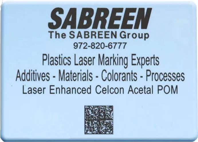
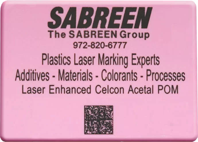
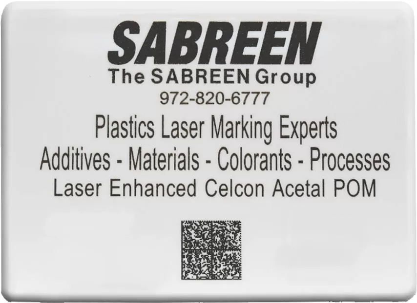
SABREEN utilizes laser-specific carbon blacks, titanium dioxides to produce superior contrast quality and line edge detail compared to conventional colorant compounds. Plastics containing the incorrect type and loading of carbon black or titanium dioxide produce subpar and illegible marking results. We have numerous alternatives to antimony-doped tin oxides for applications that require FDA and regulatory compliance.
Industrial Laser Marking Experts
Single-Source Total Solutions for Plastics Laser Marking - Material Science through Custom Systems Integration.
Technical Services
- Custom laser color match formulations & compounds, regulatory compliance, prototype samples–masterbatch, pre-compounded materials (pre-color), laser laminates.
- Laser equipment systems design, turnkey systems integration & training, machine vision, custom HMI, process documentation.
- On-site problem-solving (any global location), laser process analysis & system optimization, custom vectorized artwork.
- Laser safety certification, complete application including design & CDRH Class 1 enclosure, laser safety officer (LSO) for internal audits.
- Plastics injection molding & analytical analysis, mold flow, additive-colorant dispersion/distribution.
- Job shop marking services
Laser Marking Mechanisms
For plastics laser marking, the mechanism is to irradiate the polymer with a high-energy radiation source, e.g., Ytterbium fiber laser. The radiant energy is absorbed locally by the material and converted to thermal energy which induces reactions in the target polymer substrate. For plastics laser marking operating in the Near-infrared spectrum there are three types of surface reactions: 1) Carbonization or charring, 2) Chemical change foaming and 3) Color change by degradation. All surface reactions can be achieved using one laser by changing settings (power, pulse repetition rate, marking speed) within the laser marking software. Continuous wave (CW) CO2 lasers operate at a wavelength of 10.6 microns (far infrared spectrum). CW CO2 lasers have low peak power and cannot produce high contrast markings on plastics.

Laser Marking Solutions
Industrial laser marking solutions. Plastics and colorants, laser additives, injection molding, lasers and optics, systems integration.
Laser Additives and Colorants
Laser additives are cost saving and produce superior marking contrast and faster speed.
NEW Technology
A single formulation additive produces jet black and opaque white laser marking contrast within the same cycle. Ideal solution for label replacement and ink printing on plastic bottles and molded products. FDA complaint.
Laser Marking Plastics Applications
Interior Automotive Lever
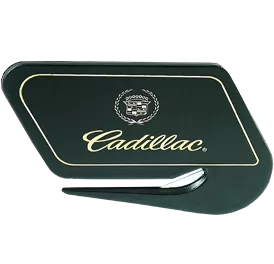
Award Winning Employee Smart Badge, RFID.
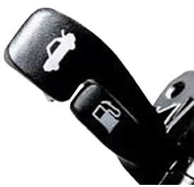
Automotive cap-less fuel filler
Medical tubing, FDA compliant for invasive surgical procedures. On-the-fly laser marking replaces ink printing.
Jet Black laser marking contrast. New additive is FDA compliant. Doesnotcontain heavy metal antimony-tin oxide/trioxide. Ideal for animals.
On-the-fly laser marking of linerless beverage closures. FDA compliant additive. Marking speed of 2,000 closures per min. HDPE, PE, Polypropylene, more.
Laser Marking Plastics Using Industrial Fiber Lasers
Ytterbium fiber lasers, MOPA, and fixed pulse are ideal for marking and engraving plastics. The functionality of a marking laser is to irradiate the part surface (polymer) with a localized high-energy radiation source (laser). The radiant energy is then absorbed by the material and converted to thermal energy. Thermal energy induces “thermal chemical” reactions to occur in the material. Laser irradiance and fluence are key parameters in plastic marking. Intensity is influenced by Pulse frequency, Laser power, Focal spot size, and Pulse width. Fluence is influenced by Beam intensity, Scanner velocity, Pulse overlap, and Focus beam diameter. Laser Intensity and Fluence parameters are carefully balanced based on the plastic type to achieve optimal quality.
Laser Marking Terminology
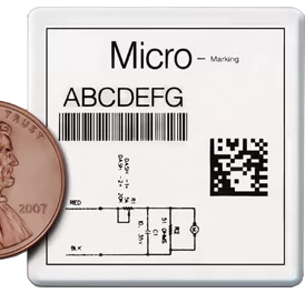
“Laser Marking” of plastics is a noncontact digital process whereby indelible information is applied onto a target substrate surface with minimal material penetration. Information is typically in the forms of alphanumeric text, symbols, graphics, logos, schematics, barcodes, machine vision codes, etc. Beam-steered Ytterbium fiber lasers (and predecessor Nd:YAG lasers arc-lamp and diode-pumped) operating at 1060-1080nm (near-infrared) possess ideal waveguide properties specific to their emission wavelength & power performance (peak & average power). Flying optics is an alternative method for part marking. Select colors of specific polymeric materials can also be marked using shorter wavelengths 532nm (frequency-doubled) and UV 355nm.
The basic mechanism of beam-steered laser marking, using a wavelength of 1060-1080nm, is to irradiate the polymer with a high-energy radiation source. The radiant energy is absorbed locally by the material and converted to thermal energy. The thermal energy, in turn, induces reactions in the material substrate. Several types of reactions are possible using the near-IR wavelength region, including charring, ablation, and chemical change. Depending upon the desired marking contrast results, vastly different chemistries and laser system parameters can be selected to achieve the preferred type of reaction.
Carbonization or charring reaction occurs when the energy absorbed raises the local temperature of the material surrounding the absorption site to a sufficiently high level that thermal degradation of the polymer is caused. In the presence of oxygen, this results in the burning of the polymer, but within the workpiece, a limited oxygen supply causes a charring of the polymer to form a black mark. The darkness of the mark is dependent on the energy absorbed as well as the material’s thermal degradation pathway.
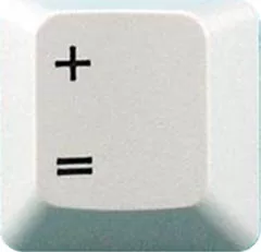
Example – ABS Computer Keycaps

Laser Etching of plastics (also known as “ablation”) is a noncontact digital process whereby a laser beam removes material from the substrate surface by vaporization or melting, with minimal penetration. The depth of a laser etch is usually no more than 0.001”. Example Daytime/night-time Automotive Buttons.
The day/night process application is to remove layers of material to expose a specific color layer. The example demonstrates a white base coating that is over-coated with one or more layers of black coating. The base polymer is typically clear Polycarbonate or ABS, both amorphous polymers to transmit (back) light from LED sources. Deeper marks into the substrate would be considered “engraving” into the material, not just etching the surface.

Laser Engraving is a deeper process than laser etching and laser marking. CW CO2 lasers operating at 10.6 ?m wavelength are typically utilized for direct colorless engraving of polymers. Another engraving application is multi-layer engraving of selective color layers (core-color & surface color), e.g., nametags, labels and signage.

Power density is a function of focused laser spot size (laser power per unit area, watts/cm2). This is different than the raw output power of the laser. Focused laser spot size for any given focal length lens and laser wavelength is a function of laser beam divergence which is controlled by laser configuration, mode selecting aperture size and upcollimator (beam expander) magnification.
Pulse repetition rate (via acousto-optic Q-switch) and peak power density are critical parameters in forming the mark and achieving the optimal contrast and speed. High peak power at low frequency increases the surface temperature rapidly, vaporizing the material while conducting minimal heat into the substrate. As the pulse repetition increases, a lower peak power produces minimal vaporization but creates more heat. Beam velocity (speed of the laser beam across the work surface) is also a critical factor.
Laser additives improve the degree of contrast, which can be further intensified by changing the laser setup parameters. Polymers possess inherent characteristics to yield “dark-colored” or “light-colored” marking contrast. Some colorant compounds containing low amounts of Titanium dioxide (TiO2) and carbon black may also absorb laser light and, in some instances, improve the marking contrast. Even within the same polymeric family, each polymer grade can produce different results. Additive formulations cannot be toxic or adversely affect the product’s appearance or physical or functional properties.
Compared to ink printing processes (pad/screen printing and inkjet), laser additives are cost-saving and demonstrate 15 percent (or greater) faster marking speeds versus non-optimized material formulations. Laser additives are supplied in pellet granulate and powder form. Granulate products can be blended directly with the polymer resin, while powder forms are converted to masterbatch. Most easily are dispersed in polymers. Based on the additive and polymer, the loading concentration level by weight (in the final part) ranges from 0.01 percent to 4.0 percent.
Both granulate and powder forms can be blended into precompounded color material or color concentrate. The selection of which additive to incorporate depends upon the polymer composition, substrate color, desired marking contrast color, and end-use certification requirements. Some additives contain mixtures of antimony-doped tin oxide and antimony trioxide that can impart a “grayish” tint to the natural (uncolored) substrate opacity. Other additives can contain aluminum particles, mixed metal oxides, and proprietary compounds.
Color adjustments are made using pigments and dyes to achieve the final colormatch appearance. As commercially supplied, specific additives (also used for laser welding) have received FDA approval for food contact and food packaging use under conditions A-H of 21 CFR 178.3297 Colorant for Polymers. For the European Union, there are similar compliance statements. Certification conditions are specific for polymer type, loading level threshold and direct or indirect contact. Further qualification of FDA-approved additives blended into a “final part” can achieve biocompatibility of medical devices (reference International Standard ISO-10993).
Achieving Faster Marking Speeds
The time required to mark a part is a function of the polymeric substrate, the number of vector lines drawn, and how fast the laser beam/galvanometer scan head draws all of the lines. Laser software and the type of vector fill, unidirectional, bidirectional, or serpentine, can also affect the marking time.
New independent studies are showing that statistically significant faster marking speeds are achievable by incorporating laser additive formulations at very low concentration levels, typically 0.01% to 2.0%.
The figure to the right shows a thermal gravimetric analysis (TGA) plot for two high-density polyethylenes. The two polymers exhibit different temperatures of thermal degradation – the process that creates the laser mark. The higher-temperature polymer will require more laser energy, lower marking speeds, or more absorbing additives to achieve the same mark appearance.

Primary Molding Operations
Following the completion of the “laser optimized” material science (which includes establishing the optimal contrast, chroma color, and laser setup parameters), the next step is to conduct a molding trial using the actual production mold tool at the proper letdown ratio. This step is critical to ensure uniform dispersion and distribution of the laser optimized color matrix. After molding, the actual product parts are laser marked to confirm the original results.
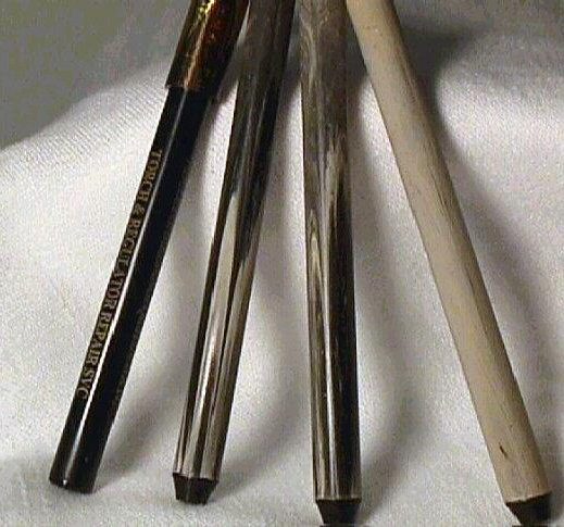
One technique is to program the beam-steered laser to continuously mark (scan) the entire product surface. The figure to the left (left to right) injection molded writing pen showing gold-on-black chroma laser marking (left), middle two pictures showing poor chroma distribution, and far-right showing excellent uniform distribution.
Processing Considerations
During the laser additive loading/colormatch chemistry, it is not uncommon for a finished product to contain less laser additive than the calculated amount. This problem almost always relates to non-uniform distribution during extrusion or molding. Simple adjustments to the molding machine, such as increasing the back pressure and screw rotation speed, will resolve most issues. Homogeneous distribution/dispersion of laser additives throughout each part is critical to achieve optimal marking performance. For extrusion, injection molding and thermoforming operations, precolor compounded materials versus color concentrate yields better uniformity. Hand-mixing should be avoided. Mold flow and gate type/location are important factors.
Not all lasers are created equal! The hardware and software components a laser manufacturer incorporate into its systems makes significant differences in marking quality, speed and versatility. When procuring laser systems, it is important to remember there is not a single universal solution. Each application is unique relative to the plastic substrate composition and color, marking quality, speed, laser efficiency, contrast (dark-on-light, light-on-dark, or color), and total system costs.
Beam quality output mode refers to the energy distribution within the laser beam and is critical to marking performance. Lasers can be supplied by manufacturers as multimode (MM), TEM00 (Transverse Electromagnetic Mode) or anything in between including Low-Order Mode (LOM). These output modes relate to factors including the beam divergence and power distribution across the diameter of the laser beam.
A TEM00 laser beam can be focused to the smallest size spot that the focusing optics permit and the energy distribution in a TEM00 laser beam is most intense at its center and tapers off uniformly from its center to its edges. TEM00 laser output provides the highest beam quality. Multi-Mode (MM) laser output provides the poorest beam quality. Reference the figure below. Low-order and TEM00 mode lasers are particularly well suited for high speed vector marking of single-stroke alphanumerics, filled true-type fonts, and complex graphics because of their ability to achieve a small focused spot with very high power densities, resulting in a very narrow line with well-defined edges that can be drawn quickly. Most plastics applications are optimal using near TEM00 or TEM00 laser beams.
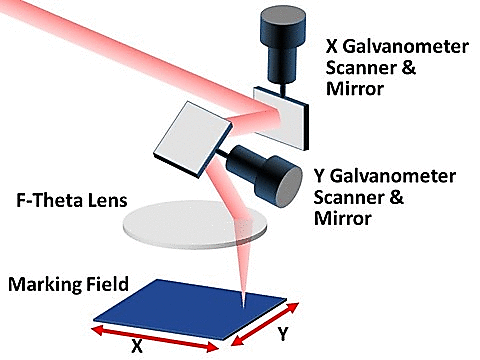
Beam-steered Nd:YAG laser markers (arc lamp and diode light sources) utilize mirrors that are mounted on high speed computer controlled galvanometers to direct the laser beam across the surface to be marked, much like writing with pencil and paper.
Each galvanometer, one on the Y-axis and one on the X-axis provides the beam motion within the marking field. A flat-field lens assembly focuses the laser light to achieve high power density on the substrate surface. The figure to the right shows Optical beam delivery system using computer-controlled galvanometers.
Fundamentally, fiber lasers are different than other solid-state marking lasers. With fiber lasers, the active medium that generates the laser beam is dispersed within a specialized fiber optic cable. In contrast to fiber-delivered lasers, the entire path of the beam is within fiber optic cable all the way to the beam delivery optics.
The advancements in laser technology have been instrumental to the rapid development of the newest generation of FDA-approved laser additives. The emergence of nanosecond Ytterbium Fiber lasers is one of the most significant advancements for marking, welding and cutting. Fundamentally, fiber lasers are different than other solid-state marking lasers. With fiber lasers, the active medium that generates the laser beam is dispersed within a specialized fiber optic cable. In contrast to fiber-delivered lasers, the entire path of the beam is within fiber optic cable all the way to the beam delivery optics.
Fiber lasers yield superior beam quality and brightness compared to Nd:YAG lasers. One metric for beam quality is M2. The smaller the M2 value, the better the beam quality, whereas M2 = 1 is the ideal Gaussian laser beam. A laser with superior beam quality can be focused to a small spot size, which leads to high energy density. Fixed and variable pulse (MOPA) fiber lasers with pulse energy up to 1 mJ and high power density can mark many historically difficult polymers. Vanadate lasers also possess a small M2 value with shorter pulse width than fixed fiber and YAG lasers. Pulse duration influences the degree of heat and carbonization into the material. Short(er) pulse width can be advantageous for sensitive polymeric applications.
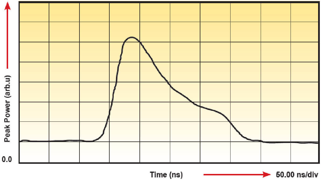
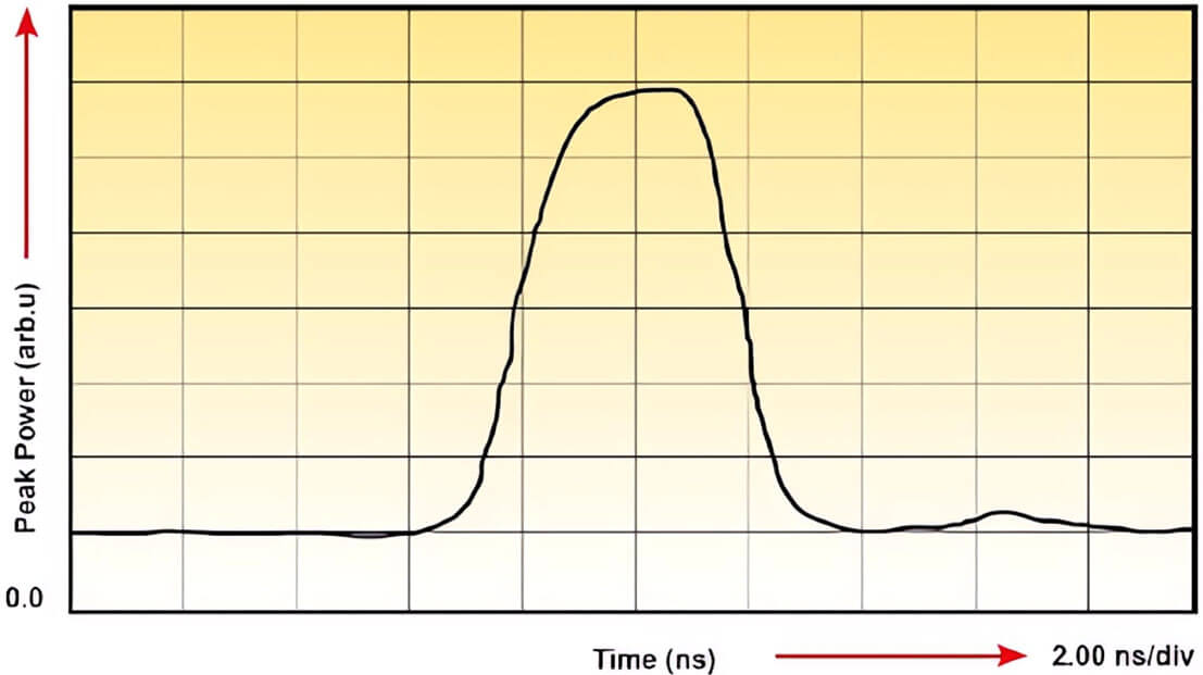
IPG Photonics, a leading developer and manufacturer of high-performance fiber lasers, offers both fixed pulse (sometimes referred to as “Q-switch”) and variable short pulse (MOPA) lasers. Application development is highly specific. The selection of which laser type to integrate is determined by the output characteristics of the laser interacting with the optimized polymer material. Reference the graphs below, representing Temporal Pulse Shapes of Fixed and Variable (MOPA) Pulse Length Ytterbium Fiber Lasers – IPG Photonics.
When setting up a fixed pulse length fiber laser for marking, two inputs must be set.
1) Pulse repetition rate (often referred to as pulse frequency)
2) Pump power in percent (100 percent refers to the maximum possible electrical input to the pump diodes)
When setting up a variable short pulse MOPA fiber laser for marking, three inputs are set.
1) Pulse duration (often referred to as pulse length)
2) Pulse repetition rate (pulse frequency)
3) Pump power in percent (100 percent refers to the maximum possible electrical input to pump diodes)
For both graphs on the previous page, the particular combination of parameter inputs controls the output properties of the laser beam, namely the pulse energy, the peak power (the highest instantaneous peak of the pulse energy, J/pulse duration) and the average power (average power in Watts = pulse energy in joules x pulse repetition rate in Hz).
Pulse repetition rate and peak power density are critical parameters in forming the mark and achieving the optimal contrast and speed. The arithmetic curves of power versus pulse repetition rate are inversely proportional. High peak power at low frequency increases the surface temperature rapidly, vaporizing the material while conducting minimal heat into the substrate. As the pulse repetition increases, a lower peak power produces minimal vaporization, but conducts more heat. Additional contributing factors that influence the marking contrast and quality are, of course, beam velocity and the vector line separation distance.
“On-the-fly” laser marking is performed on molded and extruded products, such as wire/cable, tubes and pipes. Marking speeds for polyolefin synthetic wine corks and undercap promotions on linerless beverage closures are capable of 2,000 pieces per minute for alphanumeric text and graphics. Marking speed is a function of many variables, including polymer type, substrate color, laser additive type and loading level, cable size (weight), laser type and power, software, number of alphanumeric characters, text height, length of text string, space between characters, bar code/ data matrix, logos/graphics, single-stroke or true-type filled fonts, fill direction and continuous or repeating text. Use of the proper formulated additive-colorant will ensure that “power density” at the mark surface is not the limiting factor. Rather, the beam-steered galvanometers will be operating at maximum speed.
Due to the complexity of factors influencing on-the-fly production marking capability, every application must be precisely examined. There are few, if any, rules that can be extrapolated. However, for general purposes, consider the following nylon polymer example: 50-watt fiber laser, 254mm flat field lens, 100 alphanumeric characters, 2mm height, comprising a repeating text string length of 14.68 inches with a marking time of 0.232 seconds. The calculated speed is approximately 315 linear-feet per minute.
